Abbreviations used:
HSE = Hueck Solar Energy, CSP = Concentrated Solar Power, PV = Photovoltaics
Technology
Application
System
A solar thermal plant according to the HSE concept includes, among others, the advantages listed below.
Some aspects are already mentioned in brief on the page “Overview“:
- The concept is fully industrializable as a mandatory prerequisite for achieving a competitive cost level.
- The working medium air is harmless, non-corrosive, and non-toxic.
- Due to the low system pressure, the plant does not fall under the Pressure Equipment Directive.
- The solid-state heat storage has a much longer lifespan than lithium batteries.
- The system is suitable for heat and electricity generation.
- The rotors of the steam turbine and generator contribute to grid stabilization through their rotating masses.
- In the event of a complete failure of the external energy supply, the system is fail-safe.
- The raw materials needed for plant construction are available in unlimited quantities.
- With an air-cooled condenser for the water-steam cycle and intelligent mirror cleaning methods, the water requirement for operating an HSE plant is very low.
- The overall complexity of the solar thermal plant is low.
- Very high local value creation is possible.
Additionally, the following advantages are significant:
- Only the solar thermal receiver is new; all other components are already established and bankable in terms of financing plant construction.
- The design of the receiver is robust and scalable.
- The receiver has very good technical performance data.
- The ceramic material SiC allows receiver temperatures of over 1,000 °C.
- The receiver contains no transparent components, such as quartz glass panes, which can become dirty.
- The receiver is closed to the environment and thus insensitive to contamination from the surroundings.
- The construction of the plant is not limited to horizontal surfaces for the solar field.
- Existing industrial heat processes can be partially or fully converted to the HSE concept, provided there is sufficient space at a sunny location of the heat consumer.
From the perspectives of operational reliability, availability, and cost, air is the optimal heat transfer medium.
Without a computational interpretation of the system shown and without connecting air ducts, the following are shown on the ground in a highly simplified, schematic, and clockwise manner:
- Solar tower
- Transformer building
- Air-cooled condenser
- Building for steam boiler, steam turbine, generator, and auxiliary systems
- Two air blowers
- Heat storage modules as containers for solids
Additionally, a low-loader and three cars are included.

A semicircular solar field has the following advantages:
- For a thermal application, a very short connection from the HSE plant to the heat consumer is possible.
- Due to the better incidence angle, the heliostats (mirrors) on the side of the solar tower facing away from the sun have a higher efficiency than those heliostats that would be on the opposite side.

The size of the HSE receiver block held by a steel structure in the depicted plant is chosen such that it fits onto a low-loader without disassembly into individual parts. The loaded low-loader is below the minimum clearance height of 4 meters. Given these boundary conditions, the shape of a semicircle was chosen for the solar receiver, because the inner area of a circular receiver would be too small. Accordingly, the solar field has the suitable, advantageous shape of a semicircle that matches the receiver.
The radius of the solar field is 250 meters, resulting in a total area of approximately 10 hectares. The tower has a total height of 65 meters.
With continuous daytime operation and nighttime operation up to 10 hours, the net electrical nominal power is roughly estimated at a good 1 MWel.

For larger plants, several modular receiver blocks are assembled. Each individual receiver block retains suitable dimensions for transport on a low-loader.
The maximum plant size results from the economically feasible dimensions of the air blowers and air ducts. With suitable development stages, a net nominal power in the order of 10 to 25 MWel is aimed for.
These figures are preliminary and therefore non-binding.
The minimum size of an HSE plant for electrical power generation results from the smallest possible size of a suitable steam turbine. This is in the order of less than 600 kWel.
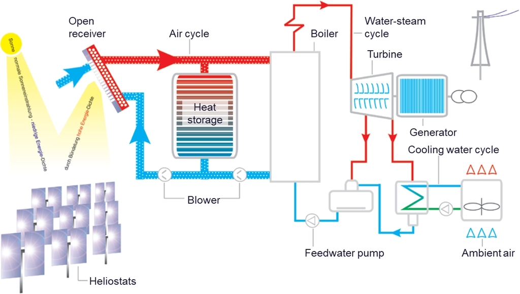
The system plan of the HSE plant shows the solar block, the thermal storage, the blowers, and the steam generator.

The solar tower power plant by Kraftanlagen München (KAM) on the premises of the German Aerospace Center (DLR) in Jülich was built between 2007 and 2008 with a nearly identical system configuration.
The only fundamental difference is the design of the receiver: The KAM receiver is open to the environment. The cold ambient air is sucked in and heated as it flows through the ceramic receiver. After the heat is released, the cooled air flows back to the receiver, where it exits into the environment and is only partially sucked in again.
With the closed HSE receiver, the risk of clogging by foreign matter from the environment is avoided.
The closed receiver can also optionally be operated with a slight overpressure. This opens up the option of blowing the hot air into a heat process without having to extract it from there again.
Receiver
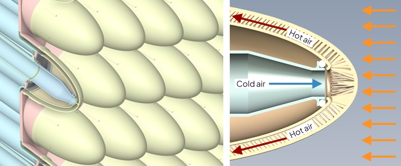
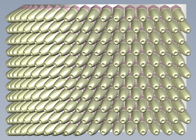
The HSE receiver uses the following technical-physical principles for the best possible heat transfer from concentrated solar radiation to the air flowing inside:
- Cold air cools best. Therefore, it is directed into the tip of each individual receiver cap, because the heat radiation from the hot outer surface there is lost unused to the environment.
- The inner surface of a receiver cap is much larger than the outer surface to achieve good heat transfer to the flowing air.
- As a material for this type of heat exchanger, silicon carbide (SiC) ceramic is very well suited. SiC ceramic has high temperature resistance in the order of 1,200 to 1,400 °C, very good thermal conductivity, high strength, and low density.
- The closely arranged receiver elements intentionally form a highly convoluted outer surface, so that the convective heat lossOn hot, vertical outer surfaces, an air current forms that carries away part of the heat. This is called convective heat loss. If such a surface is smooth, a faster current forms that carries away more heat than if such a surface is uneven. is lower than with a smooth outer surface.
- The areas further back in a receiver cap are cooled less effectively because the air has already heated up on its way to the back. However, the heat radiated from the outer surfaces there is not completely lost to the environment. Part of it strikes an adjacent surface and is transferred from there to the cooling air inside. This is called a “cavity effect” which is favorable for efficiency.
- The outer surface of the receiver is black so that the highest possible proportion of incident radiant energy is absorbed.
Most of the physical basic principles of a receiver for a solar thermal application described above were presented in 2008 by Prof. D. G. Kroger, University of Stellenbosch, South Africa, as a “Spiky Central Receiver Air Pre-heater” (SCRAP) (Kroger, 2008). As a technical application, integration into a Brayton cycle was proposed.
A further development of this approach in Stellenbosch aimed at a design in which the cooling air first flowed through a gap along the tip of the module (Erasmus, et al., 2020).
For flow guidance in a receiver module, a similar concept, developed by RWTH Aachen University and the German Solar Millennium AG, was presented to the professional audience at the SolarPACES 2012 conference (Garbrecht, et al., 2012). Additionally, a publication in a technical journal followed (Garbrecht, et al., 2013). Liquid salt was intended as the heat transfer medium.
At the Royal Institute of Technology in Stockholm, Sweden, a receiver module was also investigated, in which the heat transfer medium was initially intended to cool its tip (Wang & Laumert, 2018). The module was additionally encased externally. Here too, pressurized air for a Brayton cycle was intended as the heat transfer medium.
The basic principles of the HSE receiver were designed by Dr. Ulrich Hueck for unpressurized air as a heat transfer medium using a hand sketch on December 21, 2018, without knowing the above-mentioned similar approaches.
In the German-language final report on the joint project “SolarRetrofit“, the mentioned approaches are presented on pages 14 to 17 with further explanations and illustrations.
References:
Kroger, D. G., 2008. Spiky Central Receiver Air Pre-heater (SCRAP), Stellenbosch, South Africa: Department of Mechanical and Mechatronic Engineering, University of Stellenbosch.
Erasmus, D. J., Lubkoll, M., Craig, K. J. & von Backström, T. W., 2020. Capability of a novel impingement heat transfer device for application in future solar thermal receivers. AIP Conference Proceedings, Volume 2303, p. 030014.
Garbrecht, O., Al-Sibai, F., Kneer, R. & Wieghardt, K., 2012. Numerical Investigation of a New Molten Salt Central Receiver Design, s.l.: SolarPaces.
Garbrecht, O., Al-Sibai, F., Kneer, R. & Wieghardt, K., 2013. CFD-simulation of a new receiver design for a molten salt solar power tower. Solar Energy, Volume 90, pp. 94-106.
Wang, W. & Laumert, B., 2018. An axial type impinging receiver. Energy, 11 August, Volume 162, pp. 318-334.
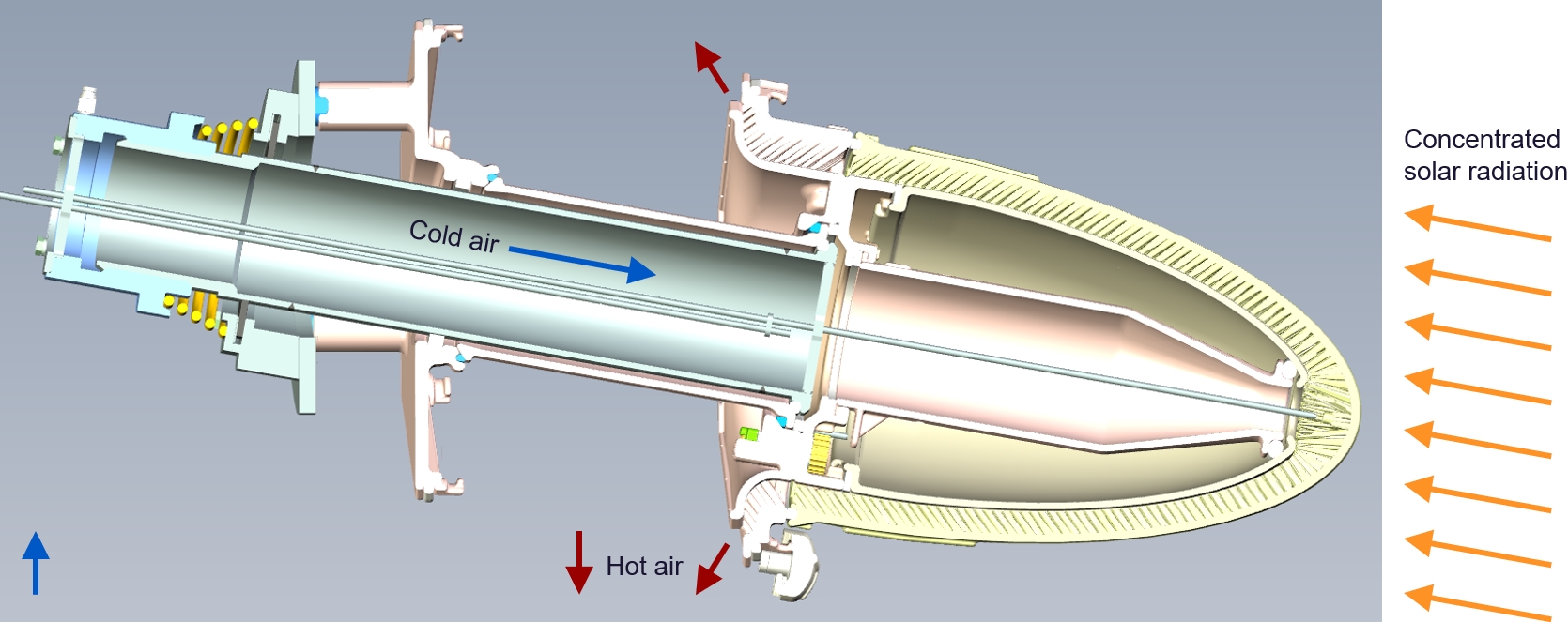
Thanks to 3D printing with the ceramic material silicon carbide (SiC), the receiver has obtained shapes that were previously impossible to manufacture.
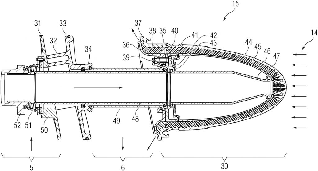
The cross-section drawing shows the internal structure of a single receiver module. The air flowing into the cold air duct enters the supply pipe from the left and flows from there into the tip of the receiver. The air is heated on its way back and then discharged downwards in the hot air duct.
The small vertical, gray surface on the left shows the supporting steel wall of the cold air duct. The receiver modules flexibly attached to this steel wall are held in position by it.
The cross-section drawing largely corresponds to an illustration in the already published patent application.
+++Partial Answer+++
A single receiver module is designed for a thermal output of 40 kWth. This applies to a temperature of 200 °C at the air inlet and a temperature of 700 °C at the air outlet.
These figures are preliminary and therefore non-binding.
If you would like to read the full answer because you are considering a collaboration with HSE, please contact us via the contact form.
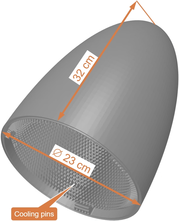
A single receiver cap has a height of approx. 32 cm and a diameter of 23 cm, so that it can be produced in 3D printing.
The receiver module shown in the photo has a length of approx. 75 cm and a weight of approx. 25 kg. Length and weight depend on the design of the width of the gray hot air duct. The circular metal part on the left, on which the ceramic back wall of the hot air duct rests, is a partial section of the large metallic wall of the cold air duct.

The individual receiver modules are assembled into a pre-assembled receiver block. The dimensions of such a block are chosen so that road transport on a low-loader is possible. The receiver block shown in the illustration has such dimensions, is semi-circular, consists of 330 modules, and provides a thermal output of approx. 13 MWth.
The radius of a receiver block is adjustable. A larger receiver can be assembled from several individual blocks arranged side-by-side and one above the other at the top of a solar tower. The actually achievable maximum receiver size depends more on the available size of the required air blower and a reasonable size of the air ducts than on the design of the receiver itself.
See also the answer to the question “Can larger systems be realized?“.
The thermal expansions of the receiver are taken into account with the following design principles, largely covered by the patent application:
- A spring element compensates for the different thermal expansions of the metallic inner tube compared to the ceramic outer tube.
- The left support of the outer tube is movable within the left back wall of the hot air duct, which is formed by individual base plates.
- The right support of the outer tube is movably mounted in the right wall of the hot air duct, which is formed by individual base plates.
- The base plates of the hot air duct, which is formed from many identical elements, are sealed against each other but not rigidly fixed together.
The ceramic production forces small components that are sealed against each other. A completely tight design is not possible. This seal is sufficient for the function of the system, even if a little energy can be lost through small leaks. Due to the system pressure of less than 500 mbar, the receiver is not a pressure vessel.
For the seven receiver modules of the Synlight test facility, the airflow of each module is adjusted by a fixed throttle plate in such a way that the most homogeneous temperature distribution possible is achieved for all modules.
For the flow distribution in a larger receiver, active control elements at the module level are planned. In this context, active regulation of the airflow will only be relevant for a portion of the modules. Such electrically driven components at the air inlet of the receiver modules will all look identical and can therefore be cost-effectively manufactured as a mass product.

A black surface absorbs more solar radiation than a light surface.
After manufacturing, the SiC ceramic has a gray surface. This is coated with the temperature-resistant paint Pyromark® 2500, which was already developed in the 1960s. The absorption coefficient thus improves from 0.856 to 0.969.
Another coating method yields a further improvement. The absorption coefficient of differently coated SiC samples is 0.982 and 0.978 after thermal stress up to 1,000 °C. This other coating method promises good durability.

The ceramic and metallic components of the receiver will have a longer service life than the seals used in the receiver. For the replacement of all seals, a receiver block consisting of many individual modules is completely replaced at night, so that this maintenance work does not negatively impact the availability of the system.
The design also allows a single defective receiver module, located within a receiver block assembly, to be almost completely replaced if necessary, without disassembling the adjacent modules.
Storage
Mirror Field
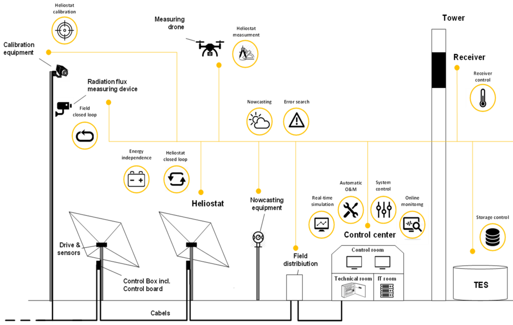
Digitalization
The control technology typical for power plants is also used in a CSP plant.
Additional control functions for the solar block include, among other things, the sub-aspects addressed in the graphic.
TES = Thermal Energy Storage
Essential geometric parameters of a receiver module and the positioning of its internal cooling pins were simultaneously optimized using software whose model can be described as artificial intelligence.
Software is also planned for optimizing the overall system, which simultaneously optimizes a multitude of parameters, representing a form of artificial intelligence.
Thus, artificial intelligence already holds significant relevance for HSE technology. Further application areas for artificial intelligence are to be expected.
Some functions of this website, such as “Open All” and “Close All”, were programmed with the help of artificial intelligence.
The operation of power plants is hardly conceivable as fully autonomous, as there are too many points where manual intervention may be required in case of doubt.
However, a large number of small solar thermal HSE plants can be operated from a single power plant control room with a very high degree of automation. All operational information for multiple plants then converges in the control room’s system. Operating personnel only need to visit an affected plant if manual intervention becomes necessary.
Power Grid
Mass Products
Green Energy Carriers
There is a connection to “green” energy carriers in two ways:
- Production of “green” energy carriers
For the nominal capacity of a facility producing electricity-based “green” energy carriers—such as hydrogen—there is either an oversupply or undersupply of fluctuating PV power throughout the day. Power from wind turbines can compensate for some of these fluctuations, but not completely. The utilization of facilities for producing “green” energy carriers—and thus their economic viability—improves significantly when an affordable power supply consistently matches the required nominal capacity. This becomes possible with a combination of PV power, wind energy, and HSE power. - Use of a “green” energy carrier
If cloud cover persists for an extended period, the heat storage of an HSE system is no longer sufficient to maintain its operation. During such periods, auxiliary firing with a “green” energy carrier can ensure a continuous heat or power supply. Thermal auxiliary firing with the “green” energy carrier iron is particularly promising.
For more information, see the section below “How does iron work as a “green” energy carrier?“
Iron burns CO2-free: Short video
The use of iron as a “green” energy carrier and its advantages are hardly known. Therefore, this process is described below in its main variant:
- Green hydrogen is produced from renewable energies:
2H2O + Electricity ➜ 2H2 + O2 - The green hydrogen extracts oxygen from oxidized (“rusted”) iron dust, producing pure iron and water vapor:
Fe2O3 + 3H2 ➜ 2Fe + 3H2O - The chemically reduced iron dust thus serves as an energy carrier.
- High temperatures are generated during the combustion / oxidation of the iron dust:
4Fe + 3O2 ➜ 2Fe2O3 + Heat
This combustion process does not produce CO2. - The now oxidised (‘rusted’) iron dust is collected and completely reused in a closed cycle.

The process has the following advantages in particular:
- The combustion of iron provides a controllable and at the same time renewable energy source that contributes to solving the problem of fluctuating energy generation from PV and wind.
- As a renewable energy source for the production of the reduced iron dust, the great potential of solar energy in sunny regions can be used: PV during the day and CSP with thermal storage at night.
- The water as a starting product for the production of green hydrogen remains at the site of production of the reduced iron and can be used there again for the production of green hydrogen. This solves the problem of the large quantities of distilled water required for the production of green hydrogen.
- The reduced iron dust can be safely transported without pressure at ambient temperature and has an energy density that is many times higher than that of hydrogen. This solves the problem of the worldwide transport of very large quantities of green energy.
- The energy carrier iron can be traded and transported globally. This results in less dependence on individual suppliers than is inevitably the case with pipelines or power lines.
- The reduced iron dust can be burned at high temperatures in coal-fired power plants and in industrial plants, which only need to be adapted in a few components. This makes it possible to continue using existing infrastructure worldwide for future green energy and electricity generation, which can result in social and financial benefits.
- No special metallic materials are used for the storage of energy in iron, where a shortage and thus a significant increase in price is to be feared, as is the case with lithium, cobalt and copper for batteries.
Renewable Iron Fuel Technology (RIFT):
- Startup: Iron Fuel Technology built for impact
- EU-Startups: Backed by €113.8 million, Dutch startup RIFT to deliver 340 GWh of industrial heat annually and avoid over 1 million tonnes of CO2
TU Darmstadt:
- Project “Clean Circles”
- Presentation “Clean Circles”
- Platform Metal Energy Hub for metal-based energy storage
HSE is not involved in the development of this technology, but a thermal co-firing with the “green” energy carrier iron is very interesting for HSE plants.
See: “Could data centers and entire economies be reliably supplied?“

Wasserstoff bei 700 bar, Ammoniak bei -34°C. Quelle: Metal Energy Hub
The company Hydrosolid promises the storage of hydrogen in a nanopolymer solid at 35 bar with 3 kWh per liter.
Comparisons
The table below summarizes technical approaches to balance non-dispatchable PV electricity. Column 2 lists the main disadvantages and Column 3 names the associated advantages of HSE technology.
|
Technology |
Disadvantages of the technology |
Advantages of the HSE system |
|---|---|---|
|
Lithium batteries |
|
|
|
Gas turbines |
|
|
|
Hydrogen for electricity generation |
|
|
|
Other CSP technologies |
|
|
|
PV electricity for heating thermal storage |
|
|
|
|

In hazy conditions, CSP parabolic trough systems have an advantage over solar tower systems: The widely distributed receiver tubes are located in the focal line of the trough-shaped mirrors. Therefore, the path that the reflected solar radiation must travel from the mirror to the receiver is very short.
In solar tower plants, the reflected solar radiation must travel a much longer, almost horizontal path through the hazy air from the mirrors to the receiver. Some energy is lost to airborne particles in the process.
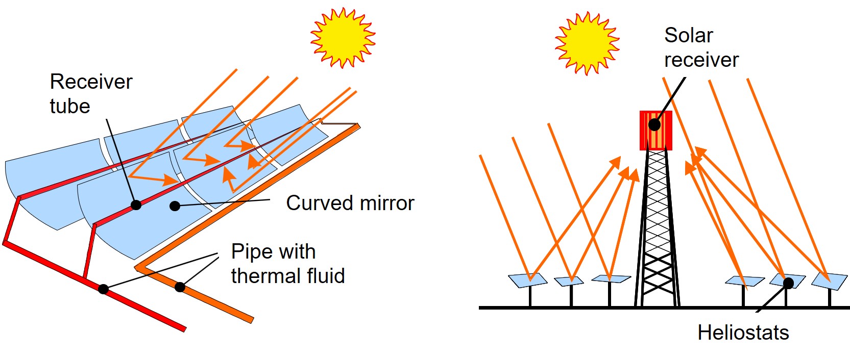
In contrast, the material expenditure for construction and the effort for operating a solar tower plant are significantly lower than for a parabolic trough plant: In a solar tower plant, the mirror field is simpler in construction, the wind loads on the mirrors are lower, and the effort for pumping the heat transfer medium through a very widely branched piping system, which must be completely sealed, is eliminated.
The large area required for a parabolic trough system must be horizontal with a gradient of no more than 3%. Otherwise, the flow of thermal oil, which serves as a heat transfer medium, would be uneven, as the low-viscosity flow in the pipes could break off when flowing downhill from an elevated position. For this reason, many locations that would otherwise be suitable for a CSP plant are ruled out for the construction of a parabolic trough system. In contrast, the mirror field of a solar tower plant is not restricted to a horizontal orientation.
Rating
Business Model
Value Creation
The HSE system largely consists of very simple plant engineering, which enables exceptionally high local value creation.
The “roll-in / roll-out” concept makes sense as a service concept for HSE systems: none of the larger components are serviced on site. Instead, they are simply exchanged for maintenance and then efficiently and cost-effectively repaired in specialized workshops.
IP Rights
The German patent application „Solar-thermal Module“ (10 2022 209 642.8) was filed on September 14, 2022, with publication on March 14, 2024.
The corresponding European patent application „Solar-thermal Module“ (PCT/EP2023/075004) was duly filed on September 12, 2023.
In March and April 2025, intellectual property rights were filed by Hueck Solar Energy GmbH on time worldwide in all countries and regions relevant to solar thermal energy.
The 11 patent claims of the patent family refer to the following sub-aspects of the solar thermal module:
- Three constructive solutions for the technical management of thermal expansions using a spring element (51), articulated connections (34, 35), and the mechanical decoupling of components (36, 37) that expand differently.
- The assignment of metallic and ceramic materials to specific functional areas (5, 30) of the solar thermal module.
- A specific aspect of flow guidance in the air outlet area (36, 37) of a solar thermal module.
- The constructive design of the form-fitting anti-rotation device for the screw connections (39, 41) inside a receiver module.
- The use of bayonet fasteners on three components (44, 46, 47) of the solar thermal module.
- The use of an outer tube (49) for supplying cold air in an inner tube (48) through the hot air duct (6).
- The method for generating thermal energy from solar radiation for a heat consumer using many such solar thermal modules (15).
Yes, the entire plant configuration is protected by the patent applications.
Indeed, for an industrializable solar tower plant using unpressurized air as a heat transfer medium, an environmentally sealed receiver is required that does not contain transparent objects such as quartz glass panes. According to the principal inventor, anyone wishing to develop or use such a receiver with good thermal efficiency will not find alternative design principles that are not covered by the patent claims.
Costs
When comparing the HSE system (CSP) with PV, two technically equivalent system configurations must be compared.
A PV system with batteries includes additional costs for grid stabilization. Rotating masses of power plants or synchronous condensers are suitable for this, but attempts are also being made to install even more batteries for this purpose. These additional costs are referred to by Lazard as “Levelized Firming Cost” (LFC) and are stated as a separate cost item, for example, for the grid operator CAISO (California Independent System Operator). If one adds the LCOE for PV plus batteries plus LFC mentioned by Lazard, then one obtains the actual LCOE of this system configuration as the middle bar in the left area of the diagram below. If one adds the same LFC to the minimum and maximum LCOE for Solar PV plus batteries (Utility) mentioned by Lazard, then the two bars on the left and right in the left area of the diagram below result.
Due to its industrialization potential, HSE technology can reach the cost corridor projected for CSP: "... the cost of electricity from CSP will potentially fall into the range of 6 to 10 US$ct/kWh.” Source: IRENA (2019), Renewable Power Generation Costs in 2018, p. 25. The lower range of this cost corridor is confirmed by the China Solar Thermal Alliance with 0.55 ¥/kWh or 7.7 US$ct/kWh for CSP plants in China in the period 2025-2027.
The HSE system (CSP) includes both storage and grid stabilization through rotating masses. This makes the industrialized HSE system a significantly more cost-effective solution.

Market
Potential customers are all medium-sized and large consumers of electricity in sunny regions. In addition, there are all medium-sized and large heat consumers in sunny regions, provided that there is sufficient space for a solar thermal system in the vicinity of the heat demand.
The explanations on the question below should be noted: “Which partners are needed for the market launch?”
For a customer who wants to obtain electricity or heat from an HSE system, the handling must be very simple. This means that a customer neither finances or builds such a plant himself, nor operates it himself, but merely pays for the energy quantities consumed.
The explanations on the question below should be noted: “Which partners are needed for the market launch?”
The output of PV systems follows a daily curve. If their area is projected onto a rectangle with the height of the systems’ peak power, then the width of this rectangle corresponds to the so-called “Peak Sun Hours“. Their duration – depending on the location – averages approximately 5 to 7 hours per day over the year. If the systems’ peak power matches the average demand of electricity consumers, then the remaining 17 to 19 “Peak Hours” per day must be supplied either from otherwise stored PV electricity or from other energy systems.
In a completely CO2-free energy supply, which largely avoids stationary electrical batteries due to enormous resource consumption and fire hazards, an industrialized and thus cost-effective CSP technology in sun-rich regions is ideally suited to cover these 17 to 19 hours per day for the most part: for electricity generation, heat generation, and the production of suitable “green” energy carriers that are globally usable.
Against this background, CSP has at least as much, if not greater, market potential than PV.
Partners
Environment
Living Beings
Space Requirements
Raw Materials
Operating Materials
Feedback
The details presented here regarding HSE technology are either already included in the disclosure of the patent application, available in the final report of a public funding project, or published elsewhere.
|
|
Template
Template Middle
Text
Text
Text